C&K systems System 236i Installation Manual
Browse online or download Installation Manual for Numeric keypads C&K systems System 236i. C&K systems System 236i Installation manual User Manual
- Page / 28
- Table of contents
- BOOKMARKS
- CAUTION: 1
- WARNING: 1
- Table of Contents 2
- WIRING THE PANEL 3
- KEYPAD SETUP 4
- SYSTEM START-UP 4
- FACTORY SETTINGS 5
- PROGRAMMING OPTIONS 5
- PROGRAMMING THE PANEL 6
- PROGRAMMING CONVERSIONS 7
- The keypad will 8
- CL 00 - 07 9
- CL 08 and 09 10
- CL 0A and 0B 11
- CL 0C - 0E 12
- CL 0F - 11 13
- CL 12 - 14 14
- CL 15 and 16 15
- CL 17 and 18 16
- CL 19 and 1A 17
- CL 1B and 1C 18
- CL 1D - 23 19
- CL 24 - 25 and A0 20
- Command Location 0C 24
- Command Location 0D 24
- Command Location 0E 24
- 5-051-191-00, Rev F 26
- © 1996 C&K Systems, Inc 26
- All Rights Reserved 26
- 236 Programming Worksheet 27
Summary of Contents
SYSTEM 236 Installation Manual5-051-191-00 Rev FConnect ground wire from door hinge to earth groundusing 16 AWG, green jacketed, solid-conductor wir
SYSTEM 236 Installation Manual10CL 08 and 09Command Location 08: Panel Control Options08001001(1) (2) (3) (4) (5) (6)Default Values#Digit Position (1
11SYSTEM 236 Installation ManualCL 0A and 0BCommand Location 0A: Communications Format1111(1) (2) (3) (4)Default Values0ADigit Position (1): Receive
SYSTEM 236 Installation Manual12CL 0C - 0ECommand Locations 0C - 0E: Receiver #1 Phone NumberOrder in which the numbers will be dialedCommand Locatio
13SYSTEM 236 Installation ManualCL 0F - 11Command Locations 0F - 11: Receiver #2 Phone NumberOrder in which the numbers will be dialedCommand Locatio
SYSTEM 236 Installation Manual14CL 12 - 14Command Locations 12 - 14: RPS Phone NumberOrder in which the numbers will be dialedCommand Location 12(1)
15SYSTEM 236 Installation ManualCL 15 and 16Command Location 15: Event Reports19DFE(1) (2) (3) (4) (5)Default Values15#Digit Position (1): Event Repo
SYSTEM 236 Installation Manual16CL 17 and 18Command Location 17: Status Events Reporting Codes - #10000(1) (2) (3) (4)Default Values17#Digit Position
17SYSTEM 236 Installation ManualCL 19 and 1ACommand Location 19: Panic Report0011(1) (2) (3) (4)Default Values19#Digit Positions (1) - (2): Panic Re
SYSTEM 236 Installation Manual18Digit Position (1): Loop 1 Alarm Report CodeCL 1B and 1CCommand Location 1B: Panel Timing1B322100(1) (2) (3) (4) (5)
19SYSTEM 236 Installation ManualCL 1D - 23Command Location 23: Door Chime Enable23000000(1) (2) (3) (4) (5) (6)Default Values#Digit Position (1): Lo
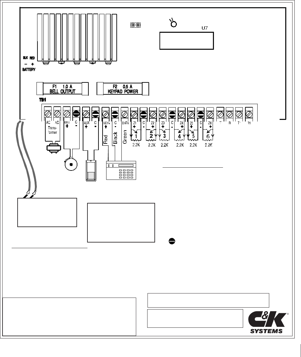
2SYSTEM 236 Installation ManualTable of ContentsSubject Page No.System 236 Terminal Label Front CoverUL Compliance 2Installation 2 - 3Wiring
SYSTEM 236 Installation Manual20Command Location 24: Shunting Enable24111111(1) (2) (3) (4) (5) (6)Default Values#Digit Position (1): Loop 1 Shuntin
SYSTEM 236 Installation Manual21TESTINGOnce the installation is complete, connect AC and DC power. Completeprogramming, if required. Test all panel
SYSTEM 236 Installation Manual22Keypad Operation Command SummaryThe majority of the keypad commands apply equally to the LED and Alpha II keypads.
SYSTEM 236 Installation Manual23QUESTION:How do I program the panel with the LED keypad?ANSWER: To program with the LED keypad, enter the Command Loca
SYSTEM 236 Installation Manual24Command Location 0C(1) (2) (3) (4) (5) (6)Command Location 0D(1) (2) (3) (4) (5) (6)Command Location 0E(1) (2) (3) (4)
SYSTEM 236 Installation Manual25Recommendations for Reducing False AlarmsThe recommendations contained in this section are designed to assist
SYSTEM 236 Installation Manual26THE LIMITATIONS OF YOUR ALARM SYSTEMWhile the SYSTEM 236 is an advanced design security system, it doesnot offer guar
SYSTEM 236 Installation Manual27236 Programming WorksheetClient: SYSTEM 236 Phone Number:Address:Installer: Date:VOLTSAC volts (AC terms):AUX POWER VO
SYSTEM 236 Installation Manual28B000000Account Number0(Last 6 digits)0Phone #1 (1st 6 digits) (Middle 6 digits)(Last 6 digits)Phone #2 (1st 6 digits)
3SYSTEM 236 Installation ManualElectromagnetic InterferenceVibrating horns can produce electromagnetic interference (EMI). WhileEMI will not damag
4SYSTEM 236 Installation ManualALPHA II KEYPAD INFORMATIONKEYPAD SETUPThe Alpha II keypad uses a top viewing display. This means the displayreads mo
5SYSTEM 236 Installation ManualAdjusting the LCD DisplayTo adjust the viewing angle, remove the keypad from the back mountingplate. Towards the botto
6SYSTEM 236 Installation ManualOption LocationFailed To Communicate Report Code 17 (3)Faulted Arming Type 08 (2)Installer Combination
7SYSTEM 236 Installation ManualData is programmed into the panel using the hexidecimal numbersystem, which consists of the digits 0 - 9 and the letter
8SYSTEM 236 Installation ManualSTAR (Shift)to other values or functions. Press and release the key first.On some keypads, this key is lab
9SYSTEM 236 Installation ManualCommand Location 00: Installer Combination00012345(1) (2) (3) (4) (5) (6)Default Values#Digit Positions (1) - (6): In
More documents for Numeric keypads C&K systems System 236i


Related products and manuals for Numeric keypads C&K systems System 236i
 (52 pages)
 (39 pages)
© 2020, manymanuals.com. All rights reserved. | 0.775 s |
 Manymanuals.com
 Manymanuals.de
 Manymanuals.fr
 Manymanuals.it
 Manymanuals.pl
 Manymanuals.cz
 Manymanuals.es
 Manymanuals-pt.com
Comments to this Manuals